

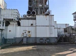

Industrial Steam Turbine
Dongturbo Electric Company Ltd. (hereinafter call "DTEC") is a professional steam turbine solution provider with ISO and CE certificate, mainly engaged in manufacturing Steam Turbines, Generators, and provide power plant EPC, EPCC and BOT solutions, also supply the equipment Spare Parts, O&M and Retrofitting Service etc.. DTEC is a manufacturing enterprise integrating steam turbine design, manufacturing, installation and service for Power Generation and Industrial Driven Purpose (Pump, Fan etc.) application in the worldwide.
The main products include all types of steam turbines, including condensing steam turbines, back pressure steam turbines, extraction steam turbines, etc. We focus on the development and promotion of single-layer quick-installation and three-station one-stop steam turbines, with high-speed, high-efficiency and energy-saving features, as well as various generators and electrical control equipment matching the steam turbines.
DTEC also can provide customers with one-stop solution for power plant project design, construction, procurement, installation, and commissioning, realizing a true turnkey project, shortening the engineering cycle for customers, and greatly reducing project costs.


Why choose us?
Quality assurance
ISO 9001 certified, Third party inspection available.
Good service
Quick response to customer requirement,Assign special personnel to dock customers.
Reaso nable price
Provide suitable solution according to customer's requirement to save cost.
Fast delivery
Focused on power industry, make reasonable stock ensureour fast delivery.
What is Industrial Steam Turbine
Industrial steam turbines use saturated or superheated pressurized steam to rotate the rotor of the steam turbine. Steam can be produced by burning fossil fuels such as natural gas, and releasing their chemical energy to heat the high-pressure liquid in the boiler tubes (water wall tubes, risers, down-comers, superheaters, and economizers). Steam can also be produced by a heat recovery steam generator (HRSG) placed, for example, at the exhaust of a gas turbine. Some steam turbines also can use the low-pressure steam of some processes to produce power.
Benefits of Industrial Steam Turbine
The benefits of steam turbines are particularly evident in the significant savings they offer. Renowned for converting thermal energy into mechanical power and subsequently into electricity efficiently, steam turbines result in a reliable power supply and substantial cost savings. Businesses investing in steam turbines often find that the initial cost pays back through reduced energy expenses, making it a financially sound decision.
One primary way steam turbines contribute to savings is through utilizing waste steam. In many industrial processes, excess steam is released into the atmosphere. Steam turbines capture this waste steam and turn it into usable electric energy, transforming what was once considered waste into a valuable resource. This practice enhances energy efficiency and reduces the need for additional energy sources, directly impacting operational expenses.
The benefits of steam turbines extend to their adaptability in various industries. From power plants to manufacturing facilities, steam turbines can be tailored to suit the specific needs of different sectors. Their versatility makes them a valuable investment for businesses aiming to optimize energy consumption and achieve sustainability goals. This adaptability ensures that the benefits of steam turbines are accessible across a wide range of industrial applications.
The longevity and durability of steam turbines contribute significantly to their cost-effectiveness. Properly maintained steam turbines can operate for decades, providing a reliable and consistent power source throughout their lifespan. The reduced need for frequent replacements or upgrades adds to the overall financial savings, making steam turbines a wise long-term investment for businesses.
Types of Industrial Steam Turbine
Small/mid-sized condensing turbines
Condensing steam turbines are employed when steady and continuous power generation is the main requirement. These turbines are recommended for plants where high reliability in power generation is required or in waste-heat recovery plants where power is generated from inexpensive fuels.
While the main steam flows through the turbine and into the condenser, steam can also be bled from the turbine for feedwater heating to increase overall plant efficiency.
Extraction-condensing turbines
Extraction-condensing turbines are employed when steady power generation and steam extraction at a fixed pressure is required. Based on the customer' s plant requirements, more than one type of extraction can be obtained from the steam turbine for processes in the plant.
Extraction pressure is controlled internally in the turbine, allowing a wide range of extraction flow rates.
Extraction can also be carried out within a wide range of operating load points.
Extraction back-pressure turbines
Extraction back-pressure turbines are employed when two or more types of process steam at different pressures are required. Process steam at required pressures is supplied through extraction openings and turbine exhaust, while generating power in the process. Electric output is dependent on the demand for process steam. If required, multiple steam extractions at different temperatures and pressures for plant processes can be supplied through extraction openings.
Mixed-pressure turbines
Mixed-pressure turbines are driven by two different types of steam (high pressure and low pressure) can also be designed for three different types of steam (high pressure, intermediate pressure and low pressure) for power generation. Hence this turbine is most suitable for applications where waste heat is recovered for power generation, such as gas turbine combined-cycle (GTCC) plants, pulp and paper factories, and cement plants. These turbines not only allow economical and optimal selection of pressure and temperature conditions for heat-recovery steam generators and boilers, but can also be used when different steams from an existing boiler and a new boiler are used to drive the turbine. If required, process steam can be extracted from the turbine, while the remaining steam is used to generate power.
Geared turbines
Geared turbines are used for small-scale power plants of up to approximately 40 MW. A speed reduction gear is installed between the generator and turbine, allowing the turbine to be designed smaller while operating at high speeds. Due to its small frame and high operating speed, geared turbines offer the following advantages over direct-coupled turbines; higher efficiency, smaller initial investment, easier maintenance, shorter delivery lead time, and smaller space requirements.
Application of Industrial Steam Turbine
Combined heat and power
Steam turbines are an essential component of most CHP systems. They support combined heat and power systems that are used to power industrial processes, under conditions where waste fuels are available for the boiler to safely utilize. When used for CHPs, the steam emitted by the steam turbine can be used directly. Steam turbine powered CHPs are typically found in paper mills, where there is an abundance of waste fuels ranging from black liquor to hog fuel, each equally successfully in powering the boiler. They can also be found in chemical plants that make excessive use of steam turbines; followed by their use of metals.
Driving mechanical equipment
Steam turbines are a far more efficient alternative to electrical power. Especially when it comes to driving different equipment like air compressors, boiler feed water pumps, refrigerator chillers, etc.
District heating & cooling systems
Different institutions throughout different cities rely on district cooling and heating systems. These systems usually have a steam turbine placed between the boiler and the distribution system or placed as a replacement for a pressure reduction station. It is to be noted that, more often, boilers are capable of producing moderate-pressure steam while the distribution requires low pressure steam. Bridging this gap between the two, a steam turbine generates energy using the high pressure steam and emits low pressure steam into the distribution system.
Combined cycle power plants
Steam turbines allow power plants to generate power using a gas turbine and utilize gas and heat produced in the process to generate steam that, in turn, produces additional power. Combined cycle power plants supported by steam turbines are capable of producing or accomplishing electric generation efficiencies extending beyond the 50-percent mark and are used in large industrial applications. Most of the electricity throughout the United States is produced with the help of steam turbine engines. Offering higher efficiencies, low costs, and a positive impact on the environment, steam turbines have become a integral part of several American industries.
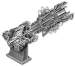
Components of Industrial Steam Turbine


Steam chest and the casing
This part is connected to the higher pressure steam supply line and the low-pressure steam exhaust line respectively. The steam chest connected to the casing houses the governor valve and the over speed trip valve. The casing contains the rotor and nozzles through which the steam is expanded and directed against the rotating buckets.
Rotor
The rotor Consists of shaft and disk assemblies with buckets. The shaft extends beyond the casing through the bearing cases. One end of the shaft is used for coupling to the driven pump and the other end of the shaft serves the speed governor and the over speed trip system.
The bearing cases
As mentioned in the rotor part, the bearing cases are connected to the rotor and support the rotor and assemble casing and steam chest. The bearing cases contain the journal bearings and the rotating oil seals, which prevent outward oil leakage and the entrance of water, dust, and steam. The steam end bearing case contains the rotor positioning bearing and the rotating components of the over speed trip system. An extension of the steam end bearing housing encloses the rotating components of the speed.
Casing sealing glands
Seal the casing and the shaft. Spring-backed segmental carbon rings used for this and supplemented by a spring-backed labyrinth section for higher exhaust-steam.
Governor system
Governor systems are speed-sensitive control systems that are integral with the steam turbine. The turbine speed is controlled by varying the steam flow through the turbine by positioning the governor valve. Consists of spring-opposed rotating weights, a steam valve, and an interconnecting linkage or servo motor system. The governor sense turbine shaft speed through direct connection, worm/worm wheel, or magnetic impulse from a gear. The turbine speed is compared to some predetermined set point and the governor output signal to a servo motor. Change in the turbine inlet and exhaust-steam conditions, and the power required by the pump will cause the turbine speed to change. The change in speed results in repositioning the governor weights and subsequent repositioning of the governor valve.
Labyrinth seal
Labyrinth is a means of reducing leakage from high pressure side to low pressure side by allowing a small amount of leakage. The clearance between labyrinth and shaft is kept at the minimum possible.
Nozzle ring and reversing blade assembly
The nozzle ring is bolted to the inside bottom half of the steam end casing. The nozzles located in the nozzle ring, direct the steam flow from the steam chest to the Curtis stage first row blades. The reversing blade assembly is located between the blade rows of the Curtis stage (the Curtis stage has two rows of blades) and is bolted to the nozzle ring. The reversing blades reverse the steam flow as it exits the first row of blades and directs the steam into the second row of blades of the Curtis stage. The reversing blade assembly is positioned axially by spacers.
Sentinel valve
This is a warning device located on the top of the exhaust end turbine casing, indicates excessive turbine exhaust end casing pressure. In the event the casing pressure exceeds a predetermined setting above the normal operating pressure, the valve releases a small amount of visible steam to the atmosphere, causing an audible sound. This valve will not serve as a relief valve.
Auxiliary steam valves
Auxiliary valves are used to achieve more efficient operation with varying load or steam conditions. The valves are provided in the steam passageway (in the bottom half of the steam end turbine casing) between the steam chest and nozzle ring. The passage is cast in three separate compartments.
One compartment is continuously open for steam flow to a bank of nozzles in the nozzle ring. The other two are fitted with auxiliary hand valves to control the flow of steam to two other banks of nozzles in the same nozzle ring.
Turning gears
Large turbines are equipped with turning gears to rotate the rotors slowly during warm-up, cool off. This is to maintain the shaft or rotor at an approximately uniform temperature circumferentially, so as to maintain straightness and preserve the balance.
Carbon ring seals
It consists of carbon ring segments and these segments held together by retaining spring. Anti-rotation stops fit in the notches in the bottom half interstage diagrams (casing) and carbon rings prevents the rotation.
Diaphragms
Stationary diaphragms separate the inner stages, contain the interstage nozzles and interstage seals. The nozzle expands the steam and direct it against the following rows of rotating blades. The diaphragms are adjusted on assembly to allow for rotor deflection and to assure that the seals are concentric with the shaft.
The bottom half of diaphragms are located vertically in the casing grooves by shims at the bottom of the grooves and laterally by means of adjusting screws at the horizontal joint. The top halves of the diaphragms are fixed in the casing by the same arrangement and lift with the casing cover.
Over-speed trip system
The trip mechanism acts independently of the governor-controlled system and closes the trip valve to stop the flow of steam to the turbine in the event of an over-speed condition. Consists of a spring-loaded pin or weight mounted in the turbine shaft on a collar, a quick-closing valve that is separate from the governor valve, and interconnecting linkage. The centrifugal force created by the rotation of the pin in the turbine shaft exceeds the spring loading at a preset speed.
Turbine cylinders
Turbine cylinders have to withstand the pressure of the steam and for this reason, they are of robust design with thick walls. They are also subject to high steam temperatures which, for thick-walled components, are not desirable. Temperature gradients within rigid components set up high stresses in the material which, when coupled with mechanical stress due to pressure, can cause the failure of the material.
How to Maintain Industrial Steam Turbine
Understanding the basics
Steam turbines are intricate machines with various components. Regularly inspect and understand each part, such as blades, seals, bearings, and casings, to identify potential issues early on.
Keep it clean
Dirt and debris can significantly impact turbine efficiency. Implement a strict cleaning regimen, especially for the intake and exhaust areas. Regularly clean blades and inspect for erosion or corrosion.
Lubrication matters
Adequate lubrication is key to preventing friction and wear. Check oil levels regularly and adhere to the manufacturer's guidelines for lubricant types and change intervals.
Monitor temperature and vibration
Unusual temperature spikes or excessive vibrations can be warning signs of potential issues. Implement a robust monitoring system to detect anomalies and take corrective action promptly.
Regular rotor balancing
Imbalances in the rotor can lead to premature wear and tear. Schedule regular rotor balancing to ensure smooth operation and extended equipment life.
Inspection and testing
Regular inspections, including non-destructive testing (NDT), are vital. This helps identify defects, cracks, or deformities that might compromise the turbine's integrity.
Regular overhaul
Plan periodic overhauls to address both preventive and corrective maintenance needs. This includes disassembly, inspection, and replacement of worn-out components.
Safety first
Prioritize safety during maintenance activities. Follow industry standards, use proper personal protective equipment (PPE), and ensure all team members are well-trained.
Embrace technology
Utilize advanced technologies such as condition monitoring, predictive maintenance tools, and digital twins to enhance your maintenance strategy and avoid unexpected downtimes.
Continuous training
Keep your maintenance team up-to-date with the latest industry trends and technologies through regular training programs. Well-trained personnel contribute to effective and efficient maintenance practices.
How Industrial Steam Turbine Works
A industrial steam turbine works by using a heat source (gas, coal, nuclear, solar) to heat water to extremely high temperatures until it is converted into steam. As that steam flows past a turbine’s spinning blades, the steam expands and cools. The potential energy of the steam is thus turned into kinetic energy in the rotating turbine’s blades. Because steam turbines generate rotary motion, they’re particularly suited for driving electrical generators for electrical power generation. The turbines are connected to a generator with an axle, which in turn produces energy via a magnetic field that produces an electric current.
Our Factory
The main parts and key components of the products have all realized CNC machining, including Japanese Mitsubishi five-axis gantry machining center, Italian tower base horizontal rotor groove milling machine, 10-meter CNC heavy-duty horizontal lathe, 8-meter CNC vertical lathe, etc., with high precision, strong reliability and advanced processing technology And other characteristics, to achieve the standardization and modularization of product components, and improve the versatility and interchangeability of product components.
