

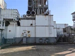

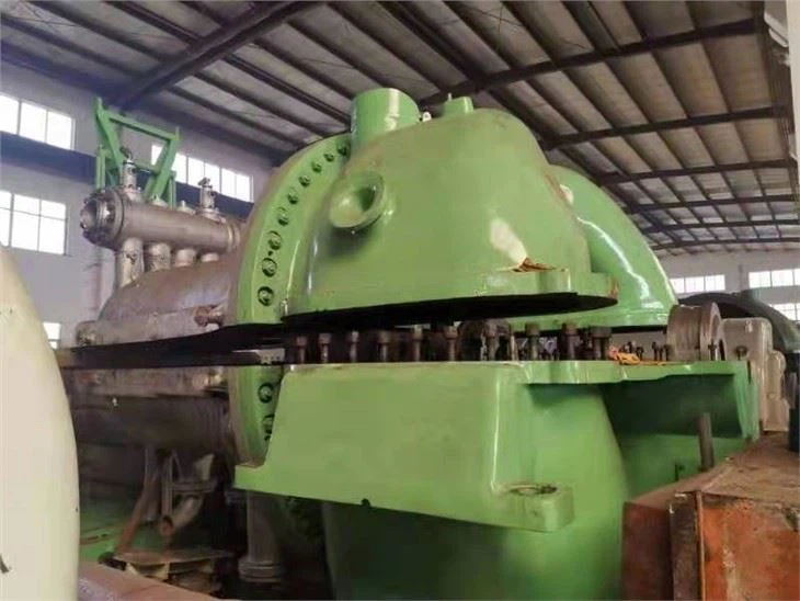

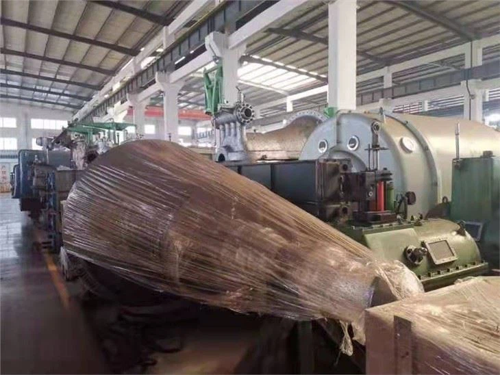
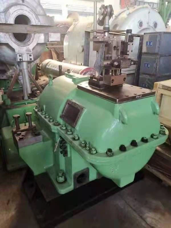

New used steam turbine/ Second hand steam turbine/ Refurbished/ in stock fast delivery within 2 months - Model N15-3.43
1. This steam turbine unit is in our factory in store which is used by client less than 6 months due to client
instead of it with more big capacity unit.
2. Price: USD 720,000/SET, FOB SHAGNHAI SEAPORT.
3. Delivery time: New used steam turbine and generator can be delivery with 2 months..
4. Technical specification and scope of supply as follows:
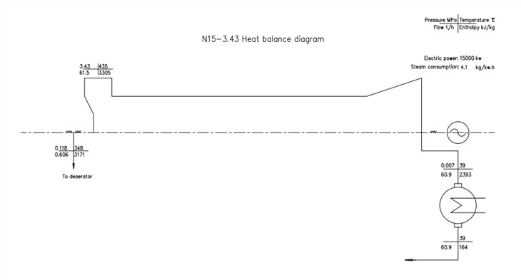
Annex: N15-3.43 Steam TurbineTechnical scheme
I. General
1、This technical agreement is applicable to the steam turbine and its supporting system of 1×15MW thermal power project, and puts forward the technical requirements of functional design, structure, performance, test and other aspects of the equipment and system.
2、The buyer put forward the minimum technical requirements in the technical agreement, but did not specify all technical requirements and applicable standards. The national mandatory standards on safety supervision and environmental protection must meet their requirements.
3、After the issuance of this technical agreement, if the buyer has anything to add or explain, it will put forward it in writing, which has the same effect as this technical agreement.
4、If there is no deviation in this technical agreement, it will be considered that the equipment provided by the seller meets the requirements in the technical agreement, and the deviation (no matter how much) must be clearly indicated in the attached difference table.
5、After signing the contract, the buyer has the right to put forward some supplementary requirements due to the change of specifications, standards and regulations, and the specific items are mutually agreed by both parties.
6、The seller shall implement the standards listed in this technical agreement. In case of contradiction, the higher standard shall prevail.
II. Summary
(I) One set of condensing steam turbine unit with rated power of 15MW is installed in the project.
(II) Equipment operating environment and site conditions:
1. Equipment installation location:
2. Average outdoor temperature over the years: ×××℃
3. Extreme maximum/minimum outdoor temperature over the years: ×××××××℃.
4. Atmospheric pressure: ××××hPa
5. Average elevation of natural ground: ~×× m (Yellow Sea datum)
6. Earthquake intensity: ×× degrees
(III) Equipment use conditions
1. Operation mode of steam turbine: constant pressure operation
2. Load nature: basic load
3. Turbine layout: indoor double-layer layout
4. Installation of steam turbine: the elevation of operation layer is 7.00m.
5. Cooling mode: hyperbolic cooling tower
6. Cooling water: fresh water and clean water.
7. Frequency range: 48.5~50.5 Hz
(IV) Main technical specifications
Product model | N15-3.43 | ||
Rated power | MW | 15 | |
Rated speed | r/min | 3000 | |
Direction of rotation | Clockwise when viewed along the steam flow direction. | ||
Rated inlet steam pressure and range of change | MPa | 3.43+0.2-0.3 (absolute) | |
Rated inlet temperature and range of change | ℃ | 435+10-15 | |
Rated steam intake/maximum steam intake | t/h | 61.5/68 | |
Cold water temperature | Masayoshi | ℃ | 25 |
Highest | ℃ | 33 | |
Rated exhaust pressure | KPa | 7 (absolute) | |
Feed water regenerative series | 1JD | ||
Design steam consumption | kg/kw.h | 4.1 | |
Guaranteed steam consumption rate under rated working conditions | kg/kw.h | 4.25 | |
Critical speed | r/min | ≈1900 | |
Vibration value at rated speed | mm | ≤0.03 (full amplitude) | |
Vibration value at critical speed | mm | ≤0.15 (full amplitude) | |
Overall dimension of steam turbine | mm | 5635*3788*2560 | |
III. Technical requirement
(I) General technical requirements
The materials, manufacturing process, inspection and testing and performance assessment requirements used for steam turbine auxiliary equipment and accessories shall conform to the standards of the former Ministry of Machinery Industry and the former Ministry of Water Resources and Electric Power and relevant enterprise standards.
The main technical standards of steam turbine are as follows (but not limited to the following standards, if there is an updated version, the latest version shall prevail):
1. GB/T5578-2007 Technical Conditions for Fixed Steam Turbine for Power Generation
2. JB/T1329-1991 Connection Dimensions of Steam Turbine and generator
3. JB/T1330-1991 Elevation and Installation Dimensions of Steam Turbine Center
4. JB/T9627-1999 Complete Supply Scope of Steam Turbine
5. JB/T8188-1999 Supply Scope of Spare Parts for Steam Turbine
6. JB/T9637-1999 Technical Conditions for General Assembly of Steam Turbine
7. JB1867-1976 Technical Conditions for Processing and Assembly of Main Components (Rotor Parts) of Steam Turbine
8. JB3330-1983 Standard for Dynamic Balance of Rigid Rotor of Steam Turbine
9. JB/T10086-2001 Technical Conditions of Steam Turbine Regulating (Control) System
10. GB/T13399-1992 "Technical Conditions of Steam Turbine Safety Monitoring Device"
1. GB12145-1989 "Steam Quality Standard for Thermal Power Steam Turbine and Steam Power Equipment"
12. GB/T8117-1987 Code for Acceptance Test of Thermal Performance of Steam Turbine in Power Station
13. JB/T9634-1999 Size Series and Technical Conditions of Steam Turbine Oil Cooler (Tube)
14. JB/T10085-1999 Technical Conditions of Steam Turbine Condenser
15. JB/T2862-1992 Technical Conditions for Packaging of Steam Turbine
16. JB/T2900-1992 Technical Conditions for Steam Turbine Paint
17. JB/T2901-1992 Technical Conditions for Rust Prevention of Steam Turbine
18. QQ/JT8187-1999 Technical Conditions for Steam Turbine Insulation
All equipment should be designed and manufactured reasonably, and can operate safely, steadily and continuously under various specified working conditions.
(II) Service life of steam turbine
1、The service life of steam turbine is not less than 30 years, and the service life of main components of steam turbine is the same as that of steam turbine.
2、The annual continuous operation hours of steam turbine should be no less than 8000 hours, the overhaul period should be no less than 3 years, and the minor repair period should be no less than 1 year.
3、Provide forced shutdown rate and availability rate of steam turbine (annual availability rate should be greater than 97%).
4、Annual availability% = (8760 hours-planned downtime hours-forced downtime hours)/(8760 hours-planned downtime hours) ×100
5、The design of steam turbine parts (excluding wearing parts) shall be able to withstand the following working conditions during their life:
starting system | number of starts | |
cold state | time | 200 |
Warm state | time | four hundred |
hot condition | time | 3000 |
Extreme heat state | time | 500 |
Load step | time | 12,000 starts at 10% |
The above-mentioned total life consumption should not be more than 75% of the service life. | ||
(III) Performance requirements of steam turbine
1、The steam turbine can run continuously and safely within the specified parameters;
2、The steam turbine can run safely and continuously at 60℃ exhaust temperature;
3、The steam turbine startup mode is constant pressure startup, and the startup curve of steam turbine is provided.
4、The critical speed of steam turbine rotor should avoid a certain range of working speed;
5、Generator can meet the island operation mode;
6、The seller shall provide the minimum load that allows long-term continuous operation of the steam turbine and the working conditions that do not allow long-term continuous operation;
7、The steam turbine should be able to run continuously at rated speed with no load for a period of time, at least to meet the time required for the test of generator with no load;
8、The shaft system of the steam turbine should be able to withstand the torque caused by sudden short circuit of the generator or non-synchronous closing;
9、The output of the steam turbine shall be measured at the outlet end of the generator;
10、 The blade does not resonate within the allowable frequency range;
11、 The vibration value of steam turbine shall conform to relevant standards;
12、 The noise value measured at 1m away from the makeup plate and auxiliary equipment of the steam turbine is lower than 90dB (A);
13、 The manufacturer shall be responsible for the unified centralized design of the vibration, critical speed, lubricating oil system and backrest wheel of the steam turbine to ensure the stability of the steam turbine.
IV. Technical requirements for structural design of steam turbine body
1、All auxiliary equipment of steam turbine are mature and advanced products;
2、The design of steam turbine flow passage should make the channel shape change smoothly to achieve higher internal efficiency;
3、The steam turbine rotor is a combined forged rotor, and the residual internal stress of the rotor should be completely eliminated. The rotor level is 15, and the high-speed dynamic balance test should be carried out before leaving the factory, and the unbalanced weight of the rotor meets the requirements of relevant standards.
4、The cylinder design considers the deformation caused by temperature gradient, and always keeps the correct concentricity. The cylinder block has enough rigidity to ensure the smooth operation and beautiful appearance of the steam turbine under various working conditions;
5、Cylinder bolts ≥M64 are equipped with heating holes for hot tightening;
6、A jacking bolt for opening the cylinder is provided;
7、Equipped with exhaust safety device to protect steam turbine and water spray cooling device to prevent high temperature of exhaust cylinder;
8、The turbine body is provided with the interface of the measuring device needed in the performance test;
9、Turning gear:
a、 Provide a complete set of electric turning gear; the device can be manually turned on the spot. The turning can start the rotor from the static state and run continuously under the normal bearing lubricating oil pressure, and the turning speed is ~ 9 rpm.
b、 The device is of manual meshing type, and the turning gear can only be put into operation when the shutdown speed reaches zero, so that the steam turbine generator can rotate from a static state, and the steam turbine rotor can be cooled evenly to avoid thermal bending.
c、 AC motor drive. In case of oil supply interruption or oil pressure drop to unsafe value during the operation of turning gear, call the police in time and stop running.
d、 Once the steam turbine starts up to a certain speed, the turning gear will automatically exit without impacting the steam turbine and not re-engaging.
10、 Turbine bearing:
a、 The steam turbine bearing is elliptical, and the design of the bearing should consider the unstable rotating speed, which has good anti-interference ability (no oil film oscillation);
b、 Under any working condition, the return oil temperature of each bearing is not more than 65℃, and the bearing metal temperature is not more than 85℃;
c、 Metal temperature measurement of bearing uses embedded platinum thermal resistor;
d、 The thrust bearing can continuously bear the bidirectional maximum thrust generated under any working condition;
11、 The front and rear steam seal structures of steam turbine can be adjusted axially;
12、 The main valve is provided with a permanent steam filter screen;
13、 Material of main turbine parts and components:
Part name | Material quality | |
Front cylinder | ZG2OCrMo | |
Rear cylinder | HT250 | |
Nozzle group | 2OCrMo | |
septum | ZG2OCrMo/HT250 | |
rotator | 30Cr1Mo1V | |
blade | 1Cr13/2Cr13 | |
Bolt and nut for horizontal split of cylinder | 35CrMoA/20CrMoA |
V. Turbine lubricating oil system
Main oil pump | Number of units | Unit | 1 |
Pressure increase | MPa | 0.883 | |
Flow quantity | l/min | 500~800 | |
High voltage electric Oil pump | Model | ||
Number of units | platform | 1 | |
Height | m | 125 | |
Flow quantity | m3/h | 40 | |
Ac auxiliary Oil pump | Model | CHY18 | |
Number of units | platform | 1 | |
Pressure force | Mpa | 0.36 | |
Flow quantity | m3/h | 18 | |
Dc auxiliary Oil pump | Model | CHY18 | |
Number of units | platform | 1 | |
Pressure force | Mpa | 0.36 | |
Flow quantity | m3/h | 18 | |
Oiler (ⅰ) | Number of units | platform | 1 |
Outlet oil pressure | MPa | 0.0883 | |
Oiler (Ⅱ) | Number of units | platform | 1 |
Outlet oil pressure | MPa | 0.196 | |
oil cooler | Type | YL-32 | |
Number of units | platform | 2 | |
Cooling area | m2 | 32 | |
Cooling oil quantity | l/min | 500 | |
Cooling water quantity | t/h | 80 | |
Cooling water temperature (max.) | ℃ | 33 | |
Oil tank | Capacity product | m3 | 3 |
Vacuum degree on oil surface | MPa | ||
Range hood | Model | CQ2-J | |
Number of units | platform | 1 |
VI. Thermodynamic system
The main equipment of the thermal system includes: condenser, steam seal system, drainage system, water jet air extractor, air pumping pipeline, water spray cooling pipeline, etc.
(I) Condenser
1、The design of condenser shall meet the standard of Technical Conditions of Steam Turbine Condenser;
2、Each steam turbine is equipped with a condenser. The condenser is designed to check the pressure of the condenser within the allowable range when the circulating water temperature is 33℃. Under low load and full load conditions, the oxygen content of condensed water should meet the water vapor quality standard;
3、The corrosion of circulating water should be fully considered for the tube and tubesheet materials of condenser, and appropriate materials should be selected or corresponding anti-corrosion measures should be taken;
4、Appropriate facilities should be provided to allow the condenser to expand freely, and the condenser should be rigidly supported;
5、The condenser should have enough vacuum pumping equipment (jet ejector) to meet the requirements of normal operation of steam turbine.
6、There should be at least one manhole door in each water chamber of the condenser, and there should be proper air discharge and water discharge joints. The condensation system is tight and does not leak steam, and the vacuum dropping speed is not more than 666 Pa/min.
7、Condenser hot well should have local water level gauge and output 4 ~ 20mA signal;
8、Technical performance of condenser:
Condenser | type | surface | |
Cooling area | m2 | 1200 | |
vapor pressure | MPa | 0.007 ~ 0.01 (absolute) | |
steam flow | t/h | ≤65 | |
Cooling water quantity | t/h | ~ 3600 | |
Cooling water temperature | ℃ | 25-33 | |
Cooling water design pressure | MPa | 0.2 (table) | |
Cooling water resistance | m | 3~6 | |
Pipe material | TP316 | ||
Dry net weight | ~ |
(II) Steam seal system
vapour lock heater | type | Shell and tube type | ||
Number of units | Unit | one | ||
heat transfer area | m2 | 20 | ||
Side pressure of water (max.) | MPa | 1.079 (absolutely) | ||
Cooling water quantity | t/h | 50 | ||
Evaporator working steaming Steam parameter | Pressure force | MPa | 0.588-1.18 | |
Wendu | ℃ | 260-435 | ||
Flow quantity | kg/h | 36 | ||
(III) Drainage system
The steam turbine body drainage system shall be able to discharge all condensate water in the steam turbine body equipment including pipelines and valves. The system can make the equipment that may be put into operation at any time always in the hot standby state.
The steam turbine provides a sufficient number of drain points to thoroughly drain and preheat.
(IV) LP heater
Low pressure heater | model | JG-40 | |
type | surface | ||
Number of units | one | ||
heat transfer area | m2 | 40 | |
Side pressure (max) | Mpa | 0.196 (absolute) | |
Side pressure of water (max) | Mpa | 0.588 (table) |
(V) Air extraction system
Water jet ejector, air extraction pipeline, valves and related accessories in the pipeline.
Technical performance of water jet ejector;
Water jet steam extractor | Model | TD-N12 | |
Number of units | one | ||
Dry air volume | Kg/h | 10.5 | |
Working water pressure | MPA | 0.39 | |
Working water quantity | T/H | ~90 |
VII. Steam turbine regulating control and protection system
Main functions of DEH:
The following control loops separately or jointly realize the functions of program-controlled start, automatic adjustment, parameter limitation, protection, monitoring and testing of the turbine.
Automatic adjustment control function:
l raising speed
After the driver's target speed is set, the unit can automatically control the regulating valve along the experience curve corresponding to the current thermal state, and complete the constant speed control of accelerating warming-up to 3000r/min. During the acceleration process, the driver can also control the acceleration process of the unit by modifying the target speed, acceleration rate, speed holding time and other means.
Automatic synchronization
After the turbine is constant speed, DEH can accept the instruction of automatic synchronizing device and automatically control the unit to synchronous speed.
Parallel grid with initial load
After the generator is connected to the grid, DEH automatically increases the given value, so that the generator can automatically take the initial load to avoid reverse power.
l Load rise
After the unit is connected to the grid, the driver can control the unit by valve control mode, power control mode, voltage control mode or CCS mode as needed, and cooperate with the boiler control system to complete the process of constant-sliding-constant-rising load.
l Valve control mode
The driver directly controls the valve opening by setting the target valve position, and DEH keeps the valve position unchanged. At this time, the unit load and steam pressure are automatically balanced.
l Power control mode
The driver controls the unit load by setting the target power, and DEH uses the turbine actual power as the feedback signal for power closed-loop control to keep the unit load unchanged. If the generator active power signal is used as the power signal, it needs to be logically processed. In addition, it should be noted that if the steam pressure of the boiler is not put into the automatic pressure regulating circuit, it is best not to operate in the power control mode.
Pressure control mode
The driver controls the pressure in front of the engine by setting the target pressure, and DEH controls the opening of the tone to keep the main steam pressure constant.
CCS mode (optional)
In CCS mode, DEH accepts the valve position given signal from CCS master controller, and directly controls the valve opening. DEH and CCS master controller can complete various control functions of machine-to-furnace, furnace-to-machine and machine-to-furnace coordination.
l Primary frequency modulation
DEH has the function of primary frequency modulation. Both power control and valve control have primary frequency modulation function.
Limit control function:
l Load limitation
The limit value is given manually, and DEH can automatically limit the load within the high and low limits.
l Low limit of main steam pressure
When the main steam pressure is lower than the limit value, DEH automatically reduces the valve opening to limit the load, so that the main steam pressure rises.
OPC control
Unit load rejection, DEH accept oil switch trip and 103% n. Overspeed signal, quickly close the regulating valve to reduce the conversion overshoot, delay for a period of time or automatically open after the speed is less than 103%no, and maintain the unit speed at 3000r/min.
Test control function:
Pseudo-grid test
After DEH presses the "False Grid-connection Test" button, it can complete the false grid-connection test in cooperation with the electric equipment.
overspeed test
The driver can operate the CRT screen, increase the speed to make the overspeed protection action check the operating speed of the impactor and the electric overspeed protection respectively. When doing mechanical overspeed test, the action value of DEH electrical overspeed protection is automatically changed from 3270r/min to 3390r/min, which is used as backup overspeed protection.
Under the control of DEH system, overspeed limit and protection test (103% and 109%) and mechanical overspeed protection test can be carried out respectively. And record the maximum speed.
103% action when DEH system closes all tone, 109% action when DEH system closes all main valves and tone.
l Valve leak test
The driver can operate the CRT screen, conduct leak test on the regulating valve and main valve, and automatically record the idle time.
l Friction test
DEH system can enter the state of friction inspection as required. In this state, DEH system automatically turns, when the speed reaches 500r/min, stop for 3∽5 minutes, close the tone and idle the turbine. The friction inspection shall be conducted by the power plant operators. Check the friction state can be interrupted at any time, and the acceleration can be directly carried out.
l Offline simulation experiment
According to the operating characteristics of the unit, simulate the speed and power of the steam turbine, make the electro-hydraulic control system form a closed-loop control system, check the integrity of the whole control system, and can also be used to train operators.
Protection control function:
l System state monitoring
There is a fault alarm light plate on CRT, which can easily find the alarm items. Important signals such as tripping, tripping and quick closing have SOE function.
l overspeed protection
When the unit is disconnected, and the speed exceeds 109%no, DEH sends a signal to interrupt the system action and quickly close the main valve and regulating valve.
Original mechanical overspeed protection, original TSI electrical overspeed protection, DEH software configuration overspeed protection, DEH speedometer hardware overspeed protection.
Function of improving automation level:
Complete automatic report copying
The driver can set the timing or event day and hour report to complete automatic recording.
Historical data record
reliability design
l The speed measurement signal adopts redundancy of two out of three.
l The design of the system conforms to the safety design principle stipulated by the International Electrotechnical Commission (IEC), and there are preventive measures for possible operation, and it can be safely shut down when the power source is lost.
l Strict tracking measures are adopted to make the switching between various modes undisturbed.
The key technical indexes
l Speed control range: turning speed ~3600r/min
l Speed control accuracy: ≤+1r/M
l Speed inequality: 3%~6% online adjustable.
l Load control range: 0~120%
l Load control accuracy: ≤+0.2% rated value
l Main steam pressure control accuracy: +0.1MPa
l Rate control accuracy: +0.1%
l System insensitivity: < 0.06%
l Speed overshoot during load rejection: < 7%, maintained at 3000r/min
l Average continuous operation time MTBF of DEH unit: ≥ 25,000 hours
l System availability: ≥99.9%
l Maximum flying speed at full load rejection < 7% h
l The system control period is less than 50ms.
VIII. Thermal insulation cover
The seller is responsible for the thermal insulation design description of the steam turbine body and main steam pipeline. At the ambient temperature of 25℃, the surface temperature of the thermal insulation layer of the steam turbine does not exceed 50℃.
IX. Electrical control requirements for instruments
(I) General requirements
1. Instrumentation and control equipment shall conform to the application principles of safety, reliability, maturity and advanced technology, and products that are eliminated or banned by the state shall not be used.
2. When designing steam turbine equipment and its system, the seller considers the safe and reasonable operation mode under various working conditions at the same time, puts forward the requirements of parameter measuring point layout, control and protection with written documents, and supplies the necessary testing and control equipment in complete sets.
3. The instruments and control equipment provided by the seller shall consider the maximum availability, reliability, controllability and maintainability, and all components shall operate in a satisfactory manner within the rated capacity under specified conditions.
4. The instruments and control equipment provided by the seller must have more than two years' mature experience in similar steam turbines in power plants, and experimental components and devices are not allowed to be used. The seller shall explain the performance of the selected equipment, including accuracy, repeatability and drift with time and temperature, etc.
5. All systems and instruments should be suitable for the environmental conditions of the factory location and the operating conditions of the equipment installation location, and the instruments and control equipment provided should be advanced technologies that have been proved today.
6. The testing elements, instruments and control equipment provided with the equipment shall be general products and conform to relevant national standards.
7. In this project, the selection of instruments and equipment should be unified as much as possible. In the absence of national general products to choose from, the seller supplies complete sets of products that have been proved by practice to be reliable in quality and meet the process requirements. In any case, instruments containing toxic substances such as mercury and products declared obsolete by the state should not be selected.
8. All instruments are qualified (non-explosion-proof) products.
(II) Turbine body instrument.
1、 Provide complete information, detailing the requirements for steam turbine measurement, control, interlocking and protection.
2、 Provide detailed thermodynamic operation parameters, including normal value, alarm value and protection action value of steam turbine operation parameters.
3、 For the thermal equipment (components) provided with the equipment, including each pressure gauge and temperature measuring element, the installation location, purpose and model specification should be explained in detail. Installation instructions for special detection devices shall be provided.
4、 The supplied indicator, switch meter and temperature measuring element must conform to the current national standards, and the products that meet the requirements of the control and monitoring system should be selected.
5、 All measuring points of the steam turbine must be located in the position where the medium is stable, representative and easy to install, and the installation position is reserved at the same time, and the relevant regulations are met.
6、 The local temperature measuring instrument adopts liquid pressure thermometer.
7、 The remote transmission (liquid pressure type) thermometer with PT100 thermal resistance is used to measure the oil return temperature of steam turbine.
8、 The embedded platinum thermal resistor with 2.0m cable is used to measure the bearing metal temperature, which is directly led to the plug seat on the steam turbine bearing seat.
9、 Armored thermocouples should be provided for measuring the metal wall temperature of steam turbines, and their length should extend beyond the insulation layer to facilitate installation and inspection.
(III) Steam turbine safety monitoring instrument system (TSI)
1, complete monitoring items, reliable performance, and steam turbine operation at the same time.
2. The seller is responsible for coordinating and solving the signals used by the equipped safety monitoring device and steam turbine, so that the monitoring system has unity and integrity, and the monitoring instruments and the signals output to the indicating instruments should be accurate and reliable.
3. The device should at least include the following functions:
a) Rotational speed measurement: have the necessary rotational speed alarm interlocking contact output; Can continuously indicate, record and give an alarm.
b) Bearing vibration: it is installed according to the number of steam turbine bearings, and the absolute vibration value of the bearing seat in the vertical direction is measured, which can be continuously indicated, recorded, alarmed and protected.
c) Axial displacement: By monitoring the displacement of the big shaft, it can continuously indicate, record, alarm and protect.
d) Cylinder expansion: measure the expansion and contraction value of the cylinder, equipped with local instruments.
e) Provide a complete TSI system including primary components, preambles, extension cables and frames, and be responsible for guiding the field debugging of the device.
4. The output signal is 4 ~ 20 mA. The same signal needs to be output all the way. If multiple signals are needed, it will be expanded in DCS.
5. For the output of control, alarm and protection contacts, it is required to send one pair of passive contacts with a capacity of 220VAC, 3A.
TSI project | 8500B/8000B |
Correspondence | Y |
Chassis position | (including power supply) |
Bearing vibration | Y |
Axial displacement | Y |
Rotation speed | Y |
Absolute expansion | Y |
Expansion difference | Y |
(IV) Pressure series instruments
1. The pressure gauge is a white dial and a black pointer, the connecting thread M20×1.5, and the dial diameter is 150mm.
2. See the scope of instrument supply for all necessary pressure gauges provided by the seller.
(V) Temperature series instruments
1、 Armored thermocouples are used to measure the metal wall temperature of steam turbine body.
2、 The local thermometer of turbine oil system adopts liquid pressure thermometer, and the remote thermometer adopts PT100 platinum thermal resistor.
3、 The local thermometer of steam turbine regenerative system adopts liquid pressure thermometer, and the remote thermometer adopts PT100 platinum thermal resistor.
4、 The seller shall provide all necessary temperature instruments (see scope of instrument supply).
(VI) Liquid level measurement
Monitor the liquid level of condenser hot well. The liquid level sensor adopts magnetic column-turning water level meter, and the magnetic float is linearly transmitted to the column-turning indicator with the change of liquid level, showing red below the liquid level and white above the liquid level, which can clearly observe the liquid level. This product can display the liquid level and output 4 ~ 20 mA (two-wire system 24VDC power supply) signal, which can be directly fed into DCS.、
X. Scope of instrument supply
Measurement location and name | on the spot | Instrument model | remarks |
I. Pressure gauge | |||
Adjusting post-stage pressure | * | Y-150 | |
exhaust steam pressure | * | Y-150 | |
Condenser pressure | * | Y-150 | |
Water ejector pressure | * | Y-150 | |
Main oil pump inlet oil pressure | * | Y-150 | |
Main oil pump outlet oil pressure | * | Y-150 | |
Lubricating oil pressure | * | Y-150 | |
Security oil pressure | * | Y-150 | |
Second, thermocouple | |||
Adjusting post-stage temperature | WRN-239 | ||
Upper and lower half temperature of cylinder | WRKK-221 | ||
Cylinder flange temperature | WRKK-221 | ||
Third, the remote thermometer (PT100) | |||
Turbine front bearing oil return temperature | * | WTYY | |
Turbine rear bearing oil return temperature | * | WTYY | |
Generator front bearing oil return temperature | * | WTYY | |
Thrust return oil temperature | * | WTYY | |
Temperature exhaust | * | WTYY | |
Steam inlet temperature of condenser
| * | WTYY | |
Condenser condensate temperature | * | WTYY | |
Iv. platinum thermal resistor Pt100 | |||
Temperature of thrust bearing pad | WZP | ||
Temperature of front and rear bearings of steam turbine | WZP | ||
Temperature of front bearing bush of generator | WZP | ||
V. TSI | 8500B/8000B | ||
DEH | ZN1000P | (including hydraulic oil station) | |
ETS |
XI. Manufacturing, testing and acceptance
1、 According to the design requirements, the physical and chemical properties of the main components of steam turbine are tested according to JB3288-1983 Physical and Chemical Inspection of Main Components of Steam Turbine.
2、 The manufacturing of the rotor shall comply with JB1867-1976 "Technical Conditions for Processing and Assembly of Main Components (Rotor Parts) of Steam Turbine", and corresponding tests shall be made.
3、 Stator manufacturing shall comply with JB3287-1983 Technical Conditions for Processing and Assembly of Main Components (Stator Parts) of Steam Turbine.
4、 The steam turbine must be assembled in the factory, and shall comply with JB/T9637-1999 Technical Conditions for Steam Turbine Assembly.
5、 The adjustment and security parts should be tested in the factory, and the performance must meet the design requirements. Regulators (including voltage regulators) and emergency protectors should be tested and calibrated in the factory to ensure reliable operation after field installation.
6、 The rotating part of steam turbine can withstand overspeed test, dynamic and static balance test of rotor. The key measurement records before and after the test shall be submitted to the buyer for inspection and confirmation by the buyer's engineer. The test speed should be 115% of the rated speed, and the deformation of each part should not exceed the elastic limit.
7、 Other parts are tested according to the regulations of the manufacturer, and the performance must meet the design requirements.
8、 All tests shall be confirmed by the buyer's engineer.
9、 The seller participates in relevant tests of steam turbine during commissioning and after commissioning, and is responsible for solving problems existing in design and manufacturing.
(I) Performance guarantee
1、 The seller shall guarantee the performance of the steam turbine specified in the main technical data and standards.
2、 In order to assess the guarantee put forward by the seller, the seller should actively participate in the formulation of the performance assessment outline, so that the buyer can conduct performance assessment tests on the steam turbine. Under rated working conditions, the guaranteed value of steam turbine performance shall not be worse than the guaranteed value proposed by the seller.
(II) Quality assurance
1、The seller shall provide the product quality certificate to ensure that the product quality is qualified. Before delivery, all parts and auxiliary machines should be inspected and tested to ensure that the whole design and manufacturing meet the requirements of regulations. Necessary factory assembly and test shall be carried out for the steam turbine and auxiliary equipment to ensure that all manufacturing and materials are free of defects, the design and processing are in line with the requirements of technical specifications, and the functions are consistent with the design requirements, and the test report shall be provided to the buyer.
2、The buyer puts forward equipment witness and manufacturing supervision requirements for main equipment to ensure that the equipment is tracked and supervised in the whole manufacturing process. On-site witness and document witness will be carried out according to the general practice of national standard for equipment witness and manufacturing supervision.
3、The seller shall, according to the requirements of ISO9001, carry out quality control and planning for the whole process from contract to equipment delivery.
(III) Technical services
Provide all-weather and all-round service for users. If you call or write, you can answer within 24 hours.
XII. Scope of supply
(I) steam turbine body:
Cylinder, diaphragm, nozzle group, guide vane ring, gland seal, bearing seat, pedestal and bearing, steam turbine rotor (with coupling), impeller blades, regulating and security sleeves, etc.
(II) Main auxiliary equipment:
Condenser, oil cooler, oil pump, steam seal heater, oil tank, jet ejector, low pressure heater, TSI, DEH and ETS.
(III) Random tools and spare parts:
1. Tools suitable for this machine, such as special wrench, hanging cylinder, hanging rotor and cylinder guide post.
2. Spare parts shall be in accordance with GB standards (such as split bolts in cylinders, gland rings, bearings, etc.).
XIII. Technical information
(I) General requirements
1、 The seller shall provide the buyer with one set of accompanying technical documents and four sets of drawings.
2、 The seller shall provide the buyer with random technical documents and drawings, and the supply time and number of drawings shall be specified in the contract.
3、 Provide the buyer with technical documents and drawings of using international units.
4、 The Seller shall provide the main specifications, standards and regulations to be followed in the design and manufacture of steam turbine body, auxiliary equipment and accessories.
5、 The provided drawings should be very detailed for the buyer's engineer to confirm and meet the requirements of construction and installation.
6、 Drawings should include sufficient details to check wiring, maintenance feasibility, convenience of field connection and overall layout.
7、 Technical documents should have numbers and drawing catalogues, and drawings should be drawn in proportion.
8、 Provide detailed installation drawings to meet the installation requirements of field instruments and control devices. The installation drawings should provide detailed actual dimensions, plane connections and correct positions on supports, and any equipment used for field installation.
(II) Technical data
1. Provide the basic drawings within 10 days after the contract comes into effect, so that the buyer can carry out the basic design.
(including the connection between steam turbine and generator, dynamic and static load, anchor bolt hole position, size, allowable acting force and torque value, thermal displacement value, lifting weight and height of installation and maintenance, etc.)
2. Provide the general design plan of the power station 15 ~ 20 days after the contract comes into effect:
Turbine nozzle diagram
general arrangement drawing
Thermal system diagram
Regulation, security and oil system diagram
Pad layout
Measuring point layout diagram
3. Provide the power station design drawings and technical data 30 ~ 45 days after the contract comes into effect:
Turbine nozzle diagram
General arrangement drawing
Thermal system diagram
Regulation, security and oil system diagram
Pad layout
Measuring point layout diagram
Steam seal pipeline
Drain pipeline
Air extraction line
Water jet air ejector
External oil pipeline system diagram
Condenser
Exhaust pipe
Parallels
Power station design drawings
Design instructions (product overview, technical specifications, main auxiliary equipment, scope of supply, consumption table of steam, water and electricity)
4. Drawings and technical data (Chinese version) provided at the time of delivery of the same equipment for checking and acceptance, installation, debugging and maintenance of the equipment:
Longitudinal profile
General arrangement drawing
Thermal system diagram
Regulation, security and oil system diagram
Load position map
Pad layout
Measuring point layout diagram
Steam cylinder
Front gland seal
Rear gland seal
Front bearing seat
Thrust front bearing
Generator front bearing
Front seat frame
Rear seat frame
Rear cylinder guide plate
Assembly spindle
Coupling
Barring gear
Emergency interrupter
Critical throttle block
Thermal expansion indicator
Regulating steam valve and connecting rod
Steam seal pipeline
Drain pipeline
Air extraction line
Water spray cooling pipeline
Steam seal steam line of heater
Main oil pump
Priming can
External oil pipeline system diagram
Condenser
Safety membrane board
Exhaust pipe
List of supply items
Supply list of accompanying documents and drawings
Installation instructions
Product quality certificate
packing list
XIV. Packaging, marking and transportation
(1) Packaging
1. Except for special parts (such as pipe fittings), all equipment and components supplied by the seller shall comply with international general standards and technical conditions for packaging, or be packed in sturdy boxes according to the best commercial practices. According to the characteristics and requirements of different goods, measures should be taken, such as proper painting or other effective anti-corrosion treatment for the equipment to meet the needs of long-distance and land/sea transportation conditions, large amount of hoisting, unloading and long-term open-air stacking, so as to prevent rain, snow, moisture, rust, corrosion, vibration and mechanical and chemical damage.
2. The technical documents provided by the supplier are properly packaged, which can withstand transportation and repeated handling, and can prevent moisture and rain erosion. Each technical document parcel contains a detailed catalogue list.
3. In order to prevent the equipment from being stolen or damaged by corrosive elements, open crates and similar packages are not used without the consent of the buyer.
Technical specification of QF-15-2 generator
I. Manufacturing standard:
GB755-2000 "quota and performance of rotating electrical machines"
GB/T7064-2002 "technical conditions of turbine synchronous motor"
GB/T7409.3-97 basic technical conditions for excitation system of large and medium-sized synchronous generators
II The technical requirements and parameters:
2.1 technical parameters
The rated capacity is 18750kVA.
The rated power is 15000kW
Rated power factor 0.8 (hysteresis)
Rated voltage 10.5kV
Rated current 1031A
Phase 3, 6 outlet terminals
Rated frequency 50Hz
The rated speed is 3000r/min
Stator connection y
Insulation class F/B
Load variation range The generator is allowed to operate under 40% ~ 110% load.
Excitation mode Microcomputer static silicon controlled excitation
Cooling mode Closed circulating air ventilation system
Direction of rotation Clockwise as viewed from the turbine end.
The effective rate is ≥97.67%.
2.2 generator technical requirements
2.2.1 Comply with relevant standards and specifications issued and implemented by the State Bureau of Technical Supervision or industry departments.
2.2.2 generator can withstand the following operation conditions:
(1) under rated power factor, the steam turbine generator set can run continuously with allowable voltage deviation from rated value of 5% and frequency deviation from rated value of less than 1%, and the output rated power is guaranteed to be 15MW;; Stable and long-term operation under the condition of 10% overshoot.
(2) When the generator stator voltage reaches 110% of the rated value and the rotor current does not exceed the rated value, continuous operation can be guaranteed.
(3) When the generator stator voltage drops to 95% of the rated value, the long-term allowable value of the stator current is not higher than 105% of the rated value.
(4) When each phase current of the generator does not exceed the rated value, three-phase unbalanced load with the ratio of negative sequence current component to rated current less than 8% is allowed, and continuous operation is guaranteed.
(5) Operating rate: the accumulative operating rate above rated, economical and half-load is guaranteed to be above 90%.
(6) The net distance between the generator terminal and the edge of the air outlet shall ensure that the ventilation requirements are met.
(7) The generator excitation system has the functions of strong excitation, under excitation and demagnetization.
(8) Other performance parameters are in accordance with relevant national and industry standards.
2.2.3 Technical requirements of excitation system
Excitation mode: self-shunt static SCR excitation
2.3 description of turbo-generator structure
The generator is mainly composed of stator, rotor, bearing, base plate and excitation system. The ventilation and cooling mode of the generator is closed self-circulating air cooling, and the cooler is placed in the pit at the lower part of the bottom plate.
2.3.1 Normal service conditions of this type of generator are:
(1) the altitude is less than 1000m.
(2) the cooling air temperature does not exceed+40℃
(3) Install in a sheltered workshop.
2.3.2 The generator operates under rated working conditions, and the allowable temperature rise limits of main components are as follows:
Main components of the generator | Temperature measurement method | Cooling air temperature 40℃ |
Fixed winding group | resistance thermometer | 80K |
Sub-winding group | resistivity method | 90K |
Stator iron core | resistance thermometer | 80K |
Bearing oil temperature/bearing shell temperature | thermometer | < 65℃/80℃ |
2.3.3 The inlet water temperature of the air cooler of the generator shall not exceed +33℃.
2.3.4 Generator body:
(1) The stator base is welded with steel plate. For the convenience of wire embedding and maintenance, the base only extends to the end plates of the iron core at both ends. The longitudinal direction of the base consists of four wall plates to form the air inlet and outlet area, which is covered by the outer cover plate and welded on both sides for climbing. The whole base structure is light and reliable.
(2) The stator core is laminated with high-quality fan-shaped silicon steel sheets. Both sides of the fan-shaped sheet are coated with insulating paint film, and the iron cores are divided into multiple grades along the axial direction, and I-shaped ventilation channel steel is supported between every two grades of iron cores to form a radial ventilation groove. The iron core is circumferentially fixed on the support rib of the base through the pigeon tail groove on the back of the yoke. The iron core is fastened along the axial direction with a fixed structure welded between the pressing ring and the outer machine wall.
(3) The stator coil adopts basket type half coil. The coil is made up of bare copper flat wire and double glass fiber coated flat copper wire at intervals. The coil insulation is a structure which is continuously wrapped and molded by mica powder tape and is treated with anti-halo. The end of the coil is made up of triangular bracket, end hoop and inter-layer annular gasket tied with alkali-free tape, and the end of the upper straight section and the upper nose end are tied with polyester sheathed glass fiber rope to form a solid whole. There are 6 outlet copper bars on the excitation side of the stator.
(4) The rotor is made of integral high-quality alloy forgings, and the transverse slot is milled on the body. A ventilation slot is provided to enhance the cooling of the end of the rotor coil.
The rotor slot insulation is a composite insulation made by baking and pressing glass grey cloth and mica powder foil. The spacer blocks for insulation under the guard ring and fixed ends are plugged with spacer blocks made of epoxy phenolic glass cloth, and then a solid whole is formed by baking and pressing technology.
The rotor slot wedge is made of hard aluminum alloy. The guard ring is a non-magnetic steel alloy forging, and a proper amount of ventilation holes are drilled to cool the end of the rotor coil.
Axial fans are installed at both ends of the rotor.
(5) The end cover is equipped with inspection window, fire extinguishing pipe and air sealing device, etc. The bottom cover is welded with steel plate, and also equipped with fire extinguishing pipe. The bottom cover at exciter end is equipped with outlet plate to support six outlet copper bars of stator.
(6) The bearing adopts sliding bearing with forced circulation of pressure oil and spherical bearing with automatic self-aligning. The bearing seat is made of cast iron, and oil baffles are installed on the bearing covers at both ends. The top of the bearing seat is equipped with a vent plug to equalize the pressure in the oil chamber. Under the bearing seat and at the flange, the pad is insulated to prevent the shaft current from passing through.
(7) The bottom plate is a split bottom plate.
(8) The generator stator is embedded with a resistance temperature measuring element for measuring the temperature of the coil and iron core.
Thermometers for measuring inlet and outlet air temperature are installed on the end cover and base.
A resistance temperature measuring device for measuring the outlet air temperature is additionally installed at the air outlet of the base, and a thermometer is also installed at the bearing oil outlet pipe.
(9) The grounding brush is installed on the bearing cover of the steam turbine side.
(10) The generator adopts radial double-flow ventilation system, and the base is divided into a wind zone with one inlet and two outlets by the middle wall. The iron core is segmented along the axial direction, with radial air ducts, and centrifugal fans installed at both ends of the rotor supply pressure to cool the motor.
(11) Static SCR excitation is used for excitation of this generator.
2.3.5 handover test
Handover test items before starting in 2.3.5.1
(1) Measurement of insulation resistance
(2) Measurement of DC resistance
(3) withstand voltage test
(4) Water pressure test of cooler
Handover test of 2.3.5.2 in running state
(1) The generator is not excited during starting. First, carry out mechanical inspection test without load to check the bearing oil temperature and bearing vibration.
(2) No-load characteristics and turn-to-turn insulation test of stator winding
5 minutes at no-load and when the stator voltage is 130% of the rated value. If the no-load voltage of the generator exceeds 30% of the rated value under the rated excitation current, it needs to be carried out under the stator voltage generated under the no-load of the generator and the rated excitation current of the rotor, but it lasts for 1 minute.
(3) Short-circuit characteristic test
(4) Load characteristic test
(5) Load temperature rise test
(6) Measure the voltage across the shaft.
2.4 Packaging, identification, transportation and storage
2.4.1 All parts of the generator shall be properly packaged according to national standards, relevant product packaging technical requirements and relevant regulations of factory standards when they are delivered. Take anti-rust measures for friction surfaces and precision mating surfaces to prevent mechanical damage. For coils, cables, leads and insulation materials, take measures such as moisture-proof, rain-proof and mechanical damage prevention.
2.4.2 The packing box shall be firm, with moisture-proof, rust-proof and shock-proof measures. The packing box shall be firm and convenient for lifting. All packing materials in the cargo boxes shall be waterproof materials such as plastics; Packing box is suitable for railway and highway transportation and hoisting.
2.4.3 The equipment identification is clear, eye-catching and beautiful, and the transportation and hoisting identification is marked on the outside of the packing box, which must be clear and in line with relevant national standards.
2.4.4 After the generator parts are transported to the installation site, they shall be stored in a sheltered warehouse. Coils, cables, leads and insulation materials should be stored in a rain-proof and moisture-proof dry warehouse.
During the storage period of generator parts at the construction site, all the parts should be inspected regularly (at least once every three months), and the parts found to be corroded and moldy should be cleaned up in time, and treated with rust prevention and moisture prevention.
2.6 Scope of supply
QF-15-2 scope of supply of turbo-generator
No. | Item | unit | quantity | |
1 | generator body (including stator, rotor, bearing, end cover, bottom plate, cooler, shim, anchor bolt, temperature measuring element, filter, brush holder and brush) | Unit | 1 | |
2 | Dual-microcomputer dual-channel static SCR excitation device (with dry transformer) | set | 1 | |
3 | special tool | Install the rotor extension shaft. | Set/power station | 1 |
4 | Spare parts | set | 1 | |
5 | random file | set | 2 | |
2.7 Spare parts
QF-15-2 List of Spare Parts for Turbogenerator
No. | Item | Qty. | unit | remarks |
1 | Bearing bush (sleeve bearing) | 1 | lot | Used for generator rear bearing |
2 | Brush D172(25×32×64) | 16 | piece | Carbon brush for generator |
3 | Brush device | 2 | piece | |
4 | With tail brush (25×32×64) | 2 | pce | Grounding brush |
2.8 Files
QF-15-2 Catalogue of Files of generator
No. | Item | Quantity (set) |
1 | Installation instructions | 1 |
2 | Electrical switch data | 1 |
3 | Generator test report | 1 |
4 | Turbine generator installation drawing | 1 |
5 | Turbine generator assembly drawing | 1 |
6 | stator | 1 |
7 | rotator | 1 |
8 | Wiring diagram of stator winding | 1 |
9 | sleeve bearing | 1 |
10 | Seat rear bearing | 1 |
11 | Temperature measurement layout | 1 |
12 | technical condition | 1 |
13 | operation instruction | 1 |
14 | Install the rotor extension shaft. | 1 |
15 | Air cooler assembly | 1 |
16 | Packing list | 1 |
2.9 Tools
QF-15-2 Installation Tool Table
No. | Item | Qty. | remarks |
1 | Install the rotor extension shaft. | 1 | One set for each power station |
Hot Tags: New used steam turbine/ Second hand steam turbine/ Refurbished/ in stock fast delivery - model N15-3.43, China, suppliers, manufacturers, factory, customized, wholesale, buy, price, cheap, bulk, quotation, discount, design, for sale, free sample, made in China, Bleed Condensing Steam Turbine, Steam Turbine Generator, Extraction Condensing Steam Turbine, Small Condensing Steam Turbine, Medium Condensing Steam Turbine, Micro Condensing Steam Turbine
You Might Also Like


Send Inquiry